![]()
HOME| TEXT| GRADING | STAFF | DEMOS | LECTURES | LABS| ELECTRONICS| PROGRAMS
(Mounting holes, adding to nets and traces)
|
The mounting holes are treated just like components. | |
|
Add them just like you did the header, except use the Layout library and the footprint is MHOLE 1. |
|
Now we need to add the header pins to the nets. | |
|
Select the Pin button
| |
|
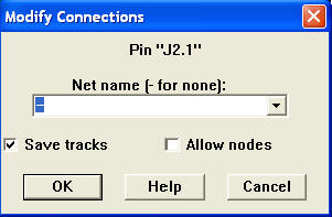
Double click on pins you want to add to a net. |
|
This shows us the name of the Pin "J2.1" and its net "-" or none in this case. | |||||||||||
|
Use the pull-down list to select the net you want, but this will only work for nets that have two or more pins in them already. | |||||||||||
|
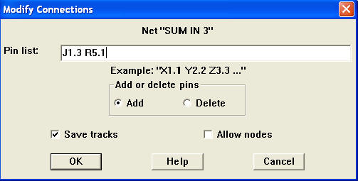
To add pins to nets that have less than two pins, you must first get the name of two pins you want to add. | |||||||||||
|
I want to add "J1.3" and "R5.1" to the "Sum In 3" net.
| |||||||||||
|
Connect all pins. | |||||||||||
|
To check which pins belong to which net, right click on a net from the spread sheet (Tool -> Net -> Select From Spreadsheet...) and go to "Properties" |
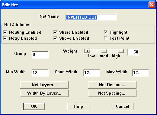
Check off "Highlight" and then press "OK" | |
Pins that belong to the net and their ratsnest are now white. |
Now it's time to lay down some traces.
| |||||||||||||||||||
Now we are ready for the Post Processes. |
Last Modified:
10/04/04
MAE433
WEBMASTER